Intro #
So I started off my IT career as an intern for a rather large company in London. I was doing a lot of misc stuff, mostly desktop but always pushed for as many networking bits I could, networking is great. A year later and here I am as a junior network engineer on the path to my CCNA (almost there!)
This post is about VLANs. VLANs in the Cisco world explained how I wish someone had explained to me. Please bear in mind that this will not be a very technical explanation, you can find that elsewhere; this will be helping you get to grips with VLANs, how they work and setting them up. Once you have a better understanding of VLANs you can go and read up some more on Ciscos website perhaps?
What is a VLAN? #
If you’ve not caught on already the term VLAN is used to describe a virtual LAN. A VLAN is used to group together devices logically instead of physically, regardless of where they may be in a room, building, city or even the world. VLANs allow for networks to be more flexible, secure and have maximum scalability. Because VLANs are their own LAN, they block broadcast messages from accessing any other VLANs, so only the machines in that VLAN will receive a broadcast which is efficient for network traffic. You can have 2 machines sitting next to each other, plugged into ports right next to each other in a switch and as long as they are in different VLANs, they will be on different networks. What should you take away from this? A VLAN is a logical group of devices that, regardless of their physical location, are in the same network and separated from other devices in different VLANs.
Why would you use a VLAN? #
I’ll give an example of a post I saw on Reddit once. Tim owns a large building and is planning on building flats, 6 of them. Tim is going to provide internet to the flats via an ethernet jack in each flat and wants to know the safest way to do this. Tim’s original plan was to get the electrician to wire up the ports in each flat into an airing cupboard and then connect these up to any old switch along with a cable from his router, providing each of the flats with a live internet connection; all the tenants have to do is plug in their own devices. There are 2 things wrong with this plan; firstly the tenants will likely plug in their own routers which will result in double NAT (not explained in this post) and secondly each of the clients in every flat will be able to communicate with each other and sniff packets. Bad. Introduce VLANs. I posted and let Tim know that what he want’s to do is to create 6 VLANs on a managed switch. A managed/smart switch is a switch that is VLAN capable either through a GUI or CLI commands. By creating 6 VLANs, assigning 6 ports on the switch to one of these VLANs and then plugging in one flat into one of these ports he has successfully isolated each of the flats from each other. Below you can see the before and after in a diagram. I helped Tim with his double NAT problem as well but maybe I’ll explain that another time.
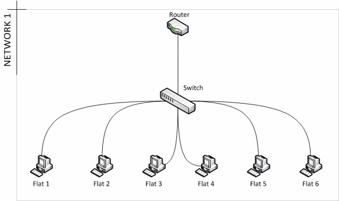
This is Tim’s original plan. All the devices behind the switch are in the same network and can communicate with each other, allowing them to discover services on each other, communicate and sniff packets.
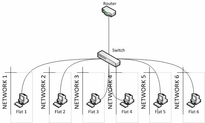
Here we have set up VLANs. You can see that each ‘flat’ has been segregated from each other and live on different networks. Now, any device plugged behind any of the ports will only be able to communicate with other devices also behind that port as they reside on the same VLAN. Attempting to access a device in another VLAN will not work.
Now imagine you had an office with 3 floors and a switch on each floor, you have a member of accounting, legal and IT on each floor and they need to be in similar networks. VLANs make this extremely easy.
- We need 3 VLANs, let’s choose 10,20 and 30. v10 is for accounting, v20 for legal and v30 for IT.
- Create VLANs 10,20 and 30 on each of the 3 switches, the switches are hooked up to each other via structured cabling throughout the building and passing the VLAN traffic (explained later).
- Assign the ports on each switch to the appropriate VLAN (explained below).
- Plug in the appropriate machine (Accounting, Legal or IT) into its corresponding port.
- Those 3 departments are now in their own separate networks and rules put in place to decide what each machine in those VLANs can and cannot access.
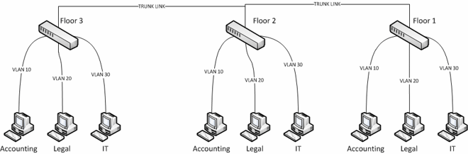
Firstly, excuse my terrible diagram, it does however do the job. You can see here that even though these people in the same department are located in different areas of the building, they are part of the same network through VLANs, allowing them to be segmented from the other departments, even if they’re sitting right next to each other and communicate with other members of their department elsewhere. The ‘TRUNK LINK’ will be explained below.
Understanding how VLANs work and communicate #
So we know that devices in the same VLAN can communicate to each other and are separated from devices in other VLANs, great. We’ve also seen how they can be used to resolve simple problems, and segment different parts of an organization, even better. I’ll attempt to explain the basics of how they work now without going into too much detail, I’ll also explain the concept behind trunk links and how switches carry VLANs between each other.
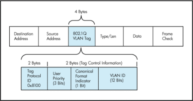
So I’ve been throwing the term VLAN around a lot, but what actually is it? A VLAN is an extra 4 bytes of data in a data packet. Part of these 4 bytes is the “VLAN ID” which tells the device what VLAN that packet belongs to so it can be routed accordingly. VLAN IDs are 1-4096, that means you may have 4096 VLANs in a network, and as per my previous example, you can use any VLAN you like in that range. You may have one network in VLAN 2 and another in VLAN 1001, it really doesn’t matter since that VLAN ID is there to identify it from any other VLAN.
What people tend to do (including me) is to have your VLAN ID in the IP range so you can easily identify which VLAN things are in. I want to say this is best practice but I’m not sure, it probably is. For example:
VLAN 10 = 172.16.10.X VLAN 20 = 172.16.20.X VLAN 30 = 172.16.30.X
Since each VLAN is its own network you will need to assign the devices different IP schemes either manually or in your DHCP server, by doing it this way it’s extremely easy to see at a glance what VLAN a machine is in and if it is supposed to be, say, in VLAN 30 and it receives an address of 172.16.20.66, you know instantly that the port it’s connected to is on VLAN 20, not 30. Okay, so we know that a VLAN is 4 bytes of additional data in a packet, and the ‘VLAN ID’ part of those 4 bytes identifies the VLAN of that data, so how do the VLANs get applied?
End devices (computer terminals, most Wi-Fi devices, printers, etc) for the most part are not VLAN aware. This means they cannot read VLAN data, and will not attach VLAN data, they don’t have to. The switch that the device is connected to will add the VLAN information when the device sends data, and will strip it when the device is reading data. Introducing, the access port. An access port (in the Cisco world, untagged port for many other vendors) is a port on a switch that is configured so that the switch itself adds the VLAN information outbound and strips that information inbound to the device. So by setting a port as an access port to say, VLAN10, you allow any device to connect to that VLAN through that port. The device is unaware that it is in that VLAN, all it knows is that it is in a network; you however know that it is in VLAN10. I mentioned that other vendors may call this an ‘untagged VLAN’, this is the same concept. A port can only have one untagged VLAN just like a Cisco device can only have one VLAN as ‘access’. To clarify; a computer/end device get’s connected to a VLAN by being plugged into a port that has been assigned that VLAN. That port is known as an ‘access port’ or an ‘untagged port’. These ports may only have one VLAN set as untagged/access.
Access VLANs #
This is a late addition to this blog post as one of the comments wanted more information on this. An access/untagged VLAN can be thought of as a ‘pass through’ VLAN. You may set as many VLANs to tagged on a port as you like, but when you plug in, say, a laptop it will always get the VLAN that is set as the access VLAN as it will not read the tagged packets. Most OSes these days will actually support tagged VLANs as virtual interfaces, you just need to configure this. Native VLAN configuration has been included below now also.
Tagging/Trunking #
So what about carrying multiple VLANs down one cable? Can it be done? Sure. This needs to happen so that switches can communicate the VLAN data between themselves. These ports in the Cisco world are called ’trunk ports’ or with other vendors ’tagged ports/tagged VLANs’. A trunk port allows the data between switches to keep their VLAN data (hence ’tagged’, the VLAN is ’tagged’). Trunk ports can have multiple VLANs travelling between them as they can read the VLAN information and pass it to the relevant network/devices. If trunk ports weren’t a thing then you would have to connect switches up with multiple cables, one for each VLAN making the port an access port on each side.
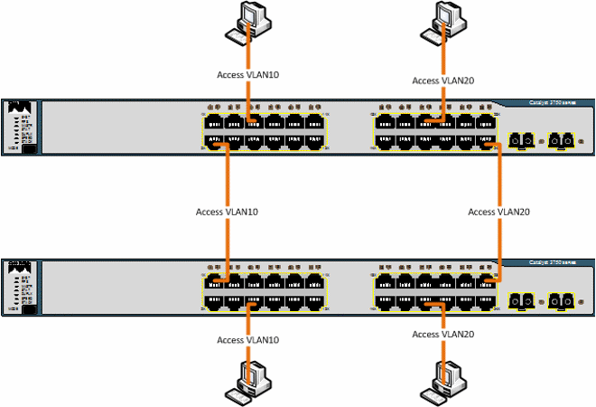
Because we know access ports/untagged ports may only have 1 VLAN, this is how we would have to connect up 2 switches so that the devices in the same VLAN can network together. Trunked ports allow for switches to understand the VLAN tags and so allowing for the following:
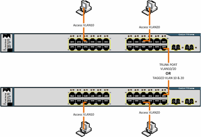
Now we are only using 1 link between the devices and we are still able to carry both VLAN10 and VLAN20 traffic between the switches thanks to this ’trunk’. As you’ll see below, on a Cisco device you will first configure a port as a trunk port and then allow VLANs onto that trunk (by default all VLANs are allowed though) whereas on a HP switch for example you would set VLAN10 as tagged and VLAN20 as tagged on both sides. I’ve been using switches as examples throughout this post however this same logic applies to any VLAN aware device, such as a hypervisor. My VM host in my lab uses 4 links in LACP (link aggregation, will cover sometime possibly) and has 6 VLANs going between the switch and the host, I can add more anytime I like. Note also that you can still have an untagged/access VLAN on a trunk port, this is called the native VLAN. Traffic passed through the native VLAN will not be changed (VLAN header).
Configuring VLANs #
So I’ll make this a 2 part deal, first being with a Cisco environment and then with a HP environment.
Configuring an access port on a Cisco device is very straightforward:
*login*
conf t - Get's into global config mode
int vlan30 - Interface VLANxxx, if VLAN doesn't exist it will be created
description TestVLAN - Set's description of VLAN, this is optional but helps you identify later on
exit - Back to global config
int fa1/0/23 - Interfacexxx, get's into selected interface config
sw access vlan30 - Sets this port to access mode on VLAN30
end - Back to privileged exec
wr mem - Writes config to flash
Configuring a trunk port is also as easy:
*login*
conf t - Get's into global config mode
int gi1/0/1 - Interfacexxx, get's into selected interface config
sw trunk encap dot1q - Set's the ports trunk mode to 802.1Q instead of the Cisco proprietary protocol, ISL
sw trunk allowed vlan remove 1-4049 - Removes all VLANs allowed to travel on trunk, only necessary if you want to keep a tight lock on your network
sw trunk allowed vlan add 30 - Adds the VLANs you want to the trunk
end - Back to privileged exec
wr mem - Writes config to flas
To add a native VLAN to a trunk port is also easy, simply run the following command on the interface:
switchport trunk native vlan xxx
And that’s it. Once you do this to both sides and connect them up you’ll have connectivity. On the HP side it’s even easier.
- Log into the switch GUI and head over to VLANs > VLAN Configuration and create your VLAN there, give it a name if you like.
- Next head over to VLANs > Participation/Tagging.
- Select your VLAN in the dropdown, in this case 30.
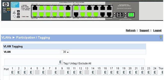
Click the port number to make that port either; E = Exclude, does not tag or untag, T = Tag VLAN to that port, U = Set that port with the selected VLAN as untagged.

Now, to add tagged VLANs and your untagged VLAN, all you need to do is set your tagged VLANs with ‘T’ and then your untagged VLAN with ‘U’.
That’s it. If you want to create a ’trunk’ then you just set multiple VLANs on the port to ‘T’. Now remember, the term ’trunk’ is only used with Cisco devices. I found this out the hard way as I was trying to create a trunk between one of my HPs and a Cisco switch. In the HP world, a trunk means link aggregation something completely different.
Voice VLAN. #
Thought I’d add this at the end because I found this extremely interesting when I was learning about it and implementing it in my homelab. A voice VLAN is a VLAN that is configured on a Cisco device that is specifically for VoIP hardware. Cisco phones, have 2 ports, an uplink port (labeled SW), and a PC port. The point behind this is that in big companies it saves on port space, instead of using 2 ports for the phone and PC you can instead plug the PC into the phone. How this works is that you set the VLAN that you want the phone to be as a Voice VLAN and the VLAN you want the PC to be in as the access VLAN. The phone then sends the access VLAN to the computer. It sounds like a trunk, it works like a trunk but Cisco say this is not a trunk and I quote; [su_quote]Cisco calls this a Multi-Vlan access port, and NOT a trunk port. if it were a trunk port, according to Cisco, it would flood all vlans configured on the switch out to the phone. As you probably know already, a port configured for voice Vlan does not flood out all Vlans to the phone, just the voice vlan frames (tagged) and the data frames ( untagged ).[/su_quote]
So that’s it! I hope this has been informative and opened up the world of VLANs to you! As I said at the start of this there is a lot more to VLANs than this but I thought it would be a good place to start. Thanks! MM~~